51单片机笔记
git test message
Based on –AT89C51.
The Atmel AT89 series is an Intel 8051-compatible family of 8 bit microcontrollers (μCs) manufactured by the Atmel Corporation.
Based on the Intel 8051 core, the AT89 series remains very popular as general purpose microcontrollers, due to their industry standard instruction set, their low unit cost, and the availability of these chips in DIL (DIP) packages. This allows a great amount of legacy code to be reused without modification in new applications. While less powerful than the newer AT90 series of AVR RISC microcontrollers, new product development has continued with the AT89 series for the aforementioned advantages.
More recently, the AT89 series has been augmented with 8051-cored special function microcontrollers, specifically in the areas of USB, I²C (two wire interface), SPI and CAN bus controllers, MP3 decoders and hardware PWM.
Data sheet url links : Data Sheet PDF Downloads
The following I would not like to just write down the points. The post will be focused on application layer
Project_1_1:TIME BOMB
It’s actually very easy to make a TIME BOMB than you can imagine.You will just need some TNT and an at89c51 chip(<3).
Now that we fixed the Bomb (got some TNT). What about the timer ? Yep, we can use the AT89C51 chip.
Timer
1 | void delayN10ms(unsigned int N){ |
what about the next to do after the timer is set? yep , light it.
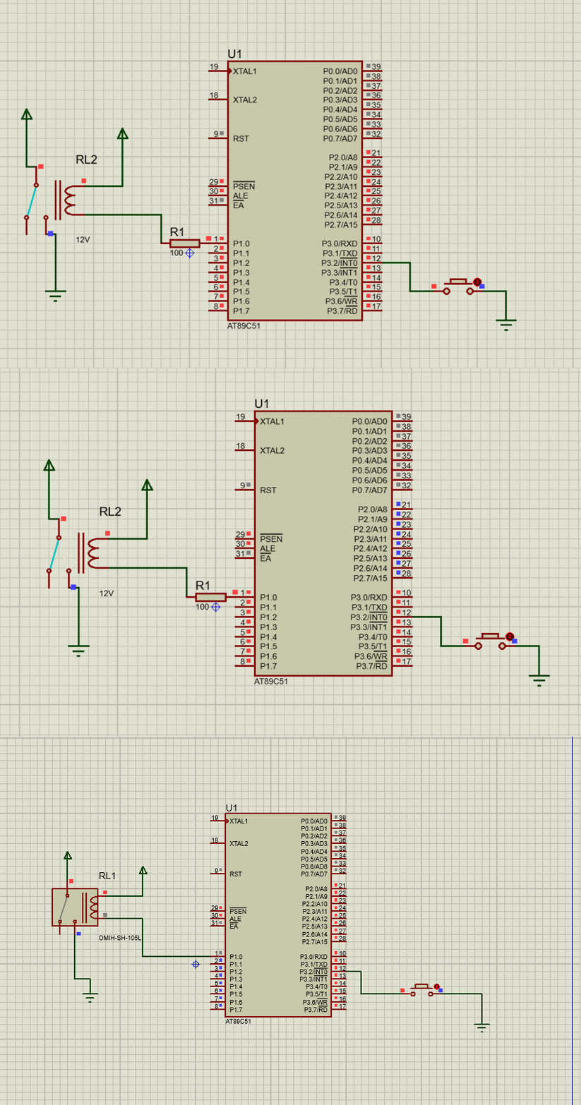
We can use a switch or a relay to light it . When the switch (connected between vcc and gnd) is on , the heat will light the TNT. EZ game.
1 | void delayN10ms(unsigned int N){ |

project_1_2 : CANCEL the TIME BOMB
Now that we create a time bomb , we are going to use it to rob a bank . However your
incompetent teammates set the bomb early! You guys are to be exposed to TNT in just 10s . What are you going to do ?
- Yes ,for sure you can reset the chip.
- Also we can use a technique called INTERRUPTION
Now we are going to talk about INTERRUPTION
The chip AT89C51 has six interrupt sources .
What is an interrupt ?
An interrupt is an external or internal event to get the CPU’s attention. Once the controller detects the interrupt, it suspends the current job and executes a special service routine know as Interrupt Service Routine(ISR).
Upon activation of an interrupt, the microcontroller goes through the following steps
First it finishes the instruction it is executing and saves the address of the next instruction (PC) on the stack.
It also saves the current status of all the interrupts internally.
It jumps to a fixed location in memory, called the interrupt vector table, that holds the address of the ISR. The microcontroller gets the address of the ISR from the interrupt vector table and jumps to it It starts to execute the interrupt service subroutine until it reaches the last instruction of the subroutine which is RETI (return from interrupt)
Upon executing the RETI instruction, the microcontroller returns to the place where it was interrupted.
First, it gets the program counter (PC) address from the stack by popping the top two bytes of the stack into the PC.
Then it starts to execute from that address.
8051 interrupt Structure
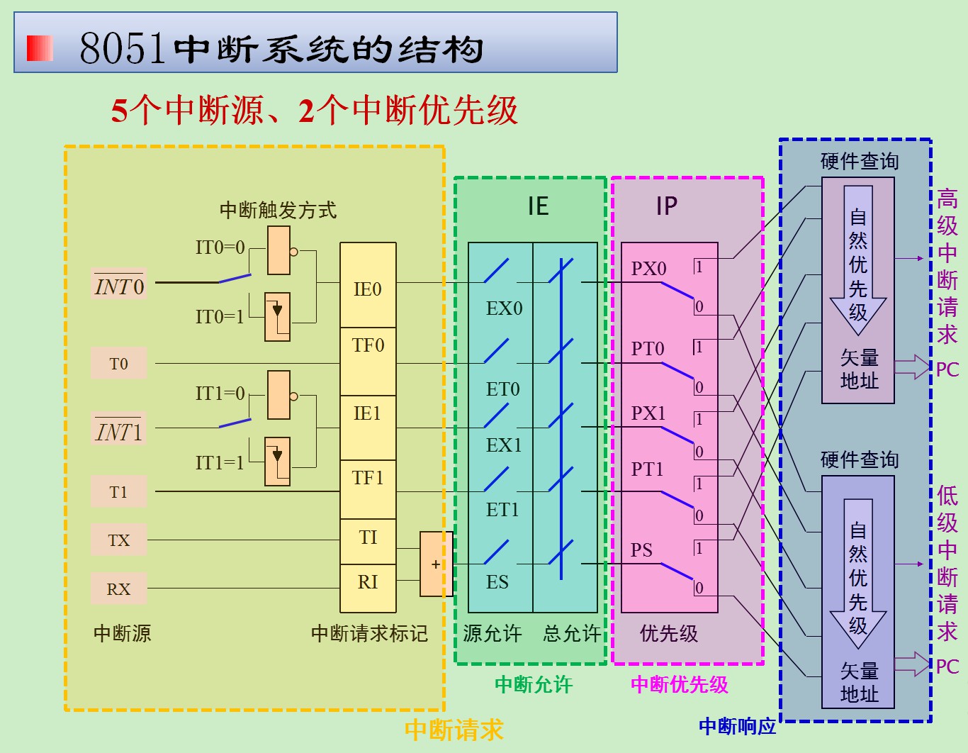
8051 Microcontroller has six interrupt sources as shown in the table below:
Interrupt ROM Location(Hex) Pin Flag Clearing Interrupt no. in C Reset 0000 9 Auto – External HW Interrupt 0 (INT0) 0003 P3.2(12) Auto 0 Timer 0 Interrupt(TF0) 000B - Auto 1 External HW Interrupt 1 (INT1) 0013 P3.3(13) Auto 2 Timer 1 Interrupt(TF1) 001B - Auto 3 Serial Com Interrupt(RI and TI) 0023 - Program SW 4
- the reset vector has just 3 bytes allocated to it, meaning it can hold a jump instruction to the location where the main program is stored.
- The other interrupts have 8 bytes allocated to each of them, hence a small Interrupt service routine(ISR) can be placed here. However, if the ISR needs to larger in length, it has to placed else where and the allocated 8 bytes need to have the code that simple redirects the control to the ISR.
- INT0 and INT1 are external interrupts on P3.2 and P3.3 respectively. These can be configured to be low level triggered or edge triggered interrupt sources.
- TF0 and TF1 are timer overflow interrupts for timer 0 and 1 respectively
- The Serial COM Interrupt can be configured to trigger upon transmit or receipt of a byte during serial communication.
enable interruption
**example code using external interrupt **
1 | void setUp(){ |
Now you can run away safely ;D.
**The above codes are just some rough examples . **
Project_1_3 : the final version of the time bomb
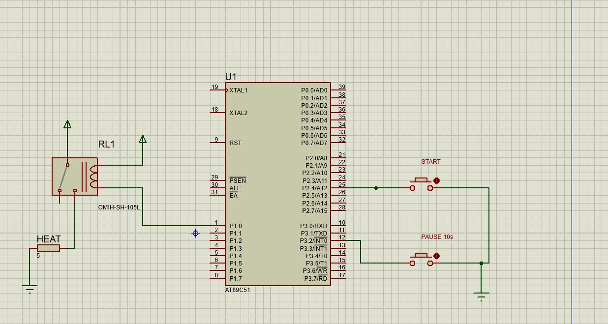
First , we are going to design the schematic seriously.

codes:
1 |
|
explanations:
- Once the bomb is set up , you need to press the start button to start the bomb.
- Once you start the bomb , you have 10 s to run away .
- If you want to delay the bomb , press the button “PAUSE” .
- ps: there is no way you can cancel the bomb unless you reset or cut off the power .
other information
1 | IT1 = 1; // Enable external interrupt 1 to trigger by a falling edge signal. |
Project_1_4: Use a TIMER interrupt to set the bomb
To control the timer and specify our needs/logic we have to configure the timers first. For configuring and controlling the 89c51 microcontroller timers we have four registers. These registers are associated with timers of 89c51 micro controller. Each register plays an important role in controlling and configuring the timer.
**Registers that are associated with timers. **
-
- (Timer Control register)
- TMOD (Timer Mode register)
- TH0/TL0 (Timer 0, 16-bit register, High bits goes to TH0, Low bits goes to TL0)
- TH1/TL1 (Timer 1, 16-bit register, High bits goes to TH1, Low bits goes to TL1)
Formula if TIMER INTERRUPT
TH0/TL0(Timer-0) = TH1/TL1(Timer-1)
These two registers TH and TL are timer high byte and timer low byte registers. 0 and 1 are the timers numbers. These are 16-bit registers. we Load our time delays/counter value in these registers. Recall 8051 timer counter can count up to 65535 and 16 bits cover 65535 in binary. Since 8051(89c51,89c52) is an 8-bit microcontroller, so to load 65535 we need two registers one representing the high byte and other the low byte. we access these register in two bytes one byte for TH(timer high byte) and TL(timer low byte). TH and TL together makes 16-bits(TH 8-bit, TL8-bit). TH0 and TL0 are byte addressable only.
- how to set them then ? There is an example .
TCON(Timer control) Register of 8051 Microcontroller
TCON(Timer Control) is an 8-bit register. It’s bits are used for generating interrupts on gpio pins internal or external. The most important bits of the timers TRx and TFx are also in it. TRx(timer run) and TFx(timer overflow) bits which we use in almost all our timer applications are in it. When we initialize TRx with 1, TRx=1 it means start the timer, When the specified time is over the timer it self make TFx=1 which means that the delay value is reached. Once TFx=1 stop the timer by initializing TRx with 0 TRx=0(Stop Timer). Now if we again want to run the timer make TRx=1. In the diagram you can see the SFR for TCON register, the bit’s used for interrupt handling and the timer run and timer over flow bits. If you want to access the individual bits of the registers, you can access them by their names. You can also access whole register it self by its name. At the bottom of the page their is a small example explaining it.
Now we are going to upgrade our Bomb!
1 |
|
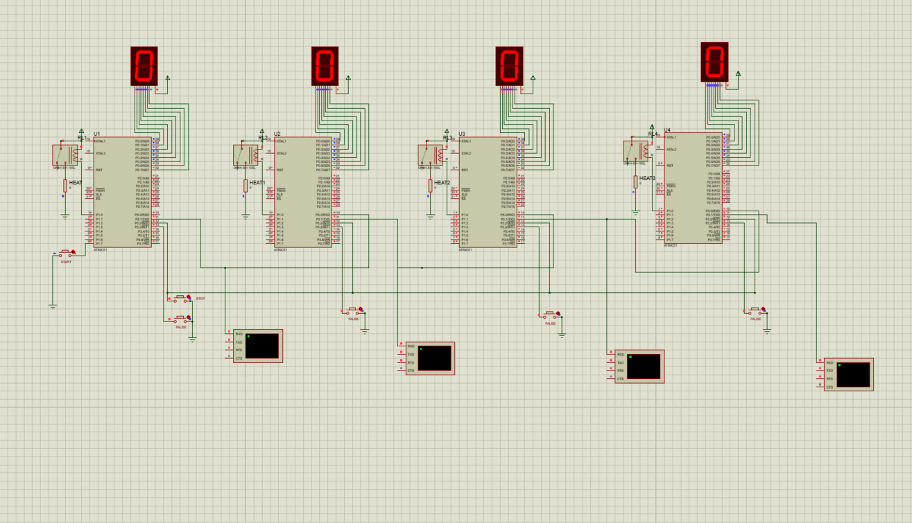
1. What if we get many BOMBs which they are set at different palces ?
- Explode with a delay ( such as 1 s )
Solution KEY :
Once the first BOMB is about to explode , it sends a signal to another BOMB.
the signal :
- Voltage (like 0 v —> 1 v or reverse it )
- Waves of Voltage ( PULSE )
- Serial text
1. Voltage
Once the first bomb is about to explode, it sends a Voltage signal to the second and so on.
We can use one of a pin to do this work .
- The first BOMB
1 | void main() |
- The second BOMB
1 | void main() |
2. Through Plain Text(by serial )
The procedure :
- Set the first bomb
- Connect to the the second Bomb and the third one so on
- Start the first Bomb
- the second before the first Bomb is about to explode ,it send a message “BOMB”
The schematic

The first BOMB.
- Transmit signal ( We only use the send module, so we just need one pin ( TX ))
1 |
|
The second BOMB
- Receive the signal from the last BOMB
- Transmit signal to the third
1 |
|
The THird BOMB.
Actually it does the same thing as the second one .
- Receive the signal from the last BOMB
- Transmit signal to the third one
1 |
|
This is the end of our BOMB
Good luck .


